|
| Elgar |
|
|
|
Àå ºñ ¸í
|
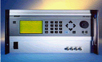
AC Power Source
|
|
¸ð
µ¨ ¸í
|
SW-3500
|
|
Á¦
Á¶ »ç
|
Elgar
|
| |
|
|
|
|
|
Àåºñ »ç¾ç |
|
|
|
|
»ç¾ç:(SPECIFICATIONS)
OUTPUT
Power Factor of Load: 0 lagging to 0 leading
AC or DC Output Voltage: 0 to 156 VRMS L-N, range 1; 0 to 312 VRMS L-N, range 2
Output Current Per Phase: 13A to 135V in 156V range; 6.5A to 270V in 312V range (per 1750 VA module)
Note: Higher currents may be achieved in 10.5-21 kVA systems.
Crest Factor: 4.0 (peak output current to RMS output current)
Output Frequency Range: DC or 40 Hz to 5 kHz. For output frequencies greater than 1 kHz, the max slew rate allowed is 1 kHz per second.
Output Power: 1750 VA: 1? 3500 VA: 1? or 2? 5250 VA: 1?or 3?(systems up to 21,000 VA)
Max Total Harmonic Distortion (Full Linear Load or No Load): 0.25% max, 40 to 100 Hz; 0.5% max to 500 Hz; and 1% max to 1 kHz plus 1%/kHz to 5 kHz
AC Noise Level: >60 dB RMS below full output voltage
Amplitude Stability With Remote Sense: ?.1% of full scale over 24 hours at constant line, load and temperature
Load Regulation: ?.025% of full scale voltage for a full resistive load to no load; above 1 kHz, add ?.01%/kHz
Line Regulation (DC, or 40 Hz to 5 kHz): ?.025% of full scale for a ?0% input line change
Voltage Accuracy: ?.1% of range. Above 1 kHz, add 0.2%/kHz. Add ?.1% of full scale for “AC PLUS DC? mode. Valid for 5 to 156 VRMS and 10 to 312 VRMS at 25°C
Voltage Resolution: 0.05% of full scale
Frequency Resolution: 0.01 Hz: 40 Hz to 99.99 Hz 0.05 Hz: 100 Hz to 999.9 Hz 0.5 Hz: 1000 Hz to 5000 Hz
Frequency Accuracy: ?.01% at 25°C ?.001%/°C Phase Accuracy, Phase-to-Phase Balanced Linear Resistive Load: ?? 40 Hz to 1 kHz, plus ??kHz above 1 kHz
Phase Angle Resolution: 0.1?
Remote Output Voltage Sense: 5 VRMS total lead drop, max
Rear Panel
1. Sync out
2. Clock and lock
3. Ext. in¡¾7.5V max
4. RS 232*
5. DFI
6. IEEE 488.2
7. Slave I/O
8. Output power terminal barrier
9. Remote sense terminal barrier
10. Fuse F1, Fuse F2, Fuse F3
11. Input, neutral
lug, single barrel
12. Safety ground
13. Chassis ground
WAVEFORM SPECIFICATIONS
Waveshape Libraries: 50 factory supplied in ROM; storage available for up to 50 user created in non-volatile RAM
Front Panel Setups: A total of 50 user created steady-state waveforms, with amplitude, frequency, phase angle and current limit parameters
Sequencing Library: 1000 user created segments stored in non-volatile RAM. Segments include waveshape, amplitude, frequency, phase angle, time (from 1 ms to 1000 seconds), or number of cycles.
MIL-STD-704 Transient Library
MEASUREMENTS (OPTIONAL)
Phase to Neutral RMS Output Voltages
Phase to Phase Voltages
1?to 3?RMS Output Currents
Peak Current n Output Frequency
1?to 3?Power
1?to 3?VA
Power Factor of 1?or 3?Loads
Output Phase Angles Relative to Phase A
Measurement Capability: 4.5 Digit Analog to Digital Measurement System with .01% of full scale resolution unless otherwise noted. All accuracies 25°±5°C
Calibration Interval: 12 months
Operating/Accuracy Temperature Range: 0°C to 45°C (32°F to 113°F) Temperature Coefficient: ?00 ppm/°C outside specified range
PHASE TO NEUTRAL RMS VOLTAGE MEASUREMENT
Valid for phases A, B and C (use phase A for Parallel Mode)
Range: 0V to 350V plus sign bit for DC range
Accuracy: ?.3% of range, DC or 47 Hz to 1 kHz; ?.5% of range, 40 to 47 Hz and for 1 kHz to 5 kHz
Phase to Phase RMS Voltage: Calculated from Phase to Neutral voltages and phase angle
Range: 0V to 700V
Accuracy and Temperature Coefficient: The same as the Phase to Neutral voltage
RMS CURRENT MEASUREMENT
Valid for phases A, B, and C (use phase A for Parallel Mode)
Range 1: 0A to 7.5A plus sign bit for DC range; 3?mode, 312V range
Range 2: 0A to 15A plus sign bit for DC range; 3?mode, 156V range
Range 3: 0A to 22.5A plus sign bit for DC range; parallel mode, 312V range
Range 4: 0A to 45A plus sign bit for DC range; parallel mode, 156V range
Accuracy: ?.0% of range, DC or 40 Hz to 500 Hz; add ?.5%/kHz above 500 Hz. Accuracies are specified for a max crest factor of 4.0.
Temperature Coefficient: ?00 ppm/°C outside specified range
Note: Contact factory for measurement range on 10.5 to 21 kVA system.
PEAK CURRENT MEASUREMENT
Valid for phases A, B, and C (use phase A for Parallel Mode)
Range 1: 0A to 28A; 3?mode, 312V range
Range 2: 0A to 56A; 3?mode, 156V range
Range 3: 0A to 84A; parallel mode, 312V range
Range 4: 0A to 168A; parallel mode, 156V range
Accuracy: ?% of range, 40 to 500 Hz; add ?%/kHz, 500 Hz to 5 kHz
Power Measurement: Valid for phases A, B, and C. Up to 3?total power and parallel mode (use phase A for parallel mode)
Range 1: 0 kW to 1.8 kW; 3?mode
Range 2: 0 kW to 5.6 kW; parallel mode and total 3?power Accuracy: ?.5% of range, DC or 40 to 500 Hz for crest factors <2.0. Add ?% for crest factors up to 4.0. Add ?%/kHz above 500 Hz VA
Measurement: Valid for phases A, B, and C. Up to 3?total VA and parallel mode (use phase A for parallel mode)
Range 1: 0 kW to 1.8 kVA; 3?mode
Range 2: 0 kW to 5.6 kVA; parallel mode and total 3? power
Accuracy: ?.5% of range, DC or 40 to 500 Hz for crest factors <2.0. Add ?% for crest factors up to 4.0. Add ?%/kHz above 500 Hz.
Power Factor: Valid for phases A, B, and C (use phase A for Parallel Mode). The Power Factor is calculated from the Power and VA measurements.
Range: 0 to 1.00
Accuracy: ?% of range at full power, DC or 40 to 500 Hz for crest factors <2.0. Add ?% for crest factors up to 4.0. Add ?%/kHz above 500 Hz.
Frequency Measurement: Frequencies are calculated based on output zero crossing time measurements.
Resolution: Frequency is displayed to 5 digits max; leading zeros are blanked. Displayed resolution is 0.01 Hz.
Accuracy: ?.5% of reading, at 10% to full output voltage, 0°C to 45°C
Phase Measurement: Valid for phases A, B, and C relative to each other
Resolution: ??
Accuracy: ?? 40 to 500 Hz; add ??kHz above 500 Hz. For sine wave, balanced resistive load, 10% to 100% of voltage measurement range
INPUT
Input Voltage Ranges: Factory configured 187 to 264 VRMS, 3?L-L (3 wire), or 342 to 457 VRMS, 3?L-L (4 wire). A chassis ground is also required. 115 or 230 VAC single-phase is required for PDU in 10.5-21 kVA systems. (400 Hz input allowed with PFC option)
Input Power Factor: 0.6 (.35 for Intl. Rectifier; 0.99 with PFC option)
Note: With PFC option the inputs may be paralleled and wired for single phase input. Consult factory.
Input Frequency Range: 47 to 63 Hz
Efficiency: 70% min., at full load
Ride Through: 3 ms min.; 10 ms min., with PFC option
PROTECTION AND SAFETY
Overvoltage Shutdown: Programmable for 20V to 255V peak, 156V range; 40V to 510V peak, 312V range
Programmable Current Limit Shutdown: Settable to 1% of range (0.5A to 13A for 156V range; 0.5A to 6.5A for 312V range)
Programmable Current Limit with Timed Shutdown: Settable to 1% of range: the timeout is settable from 10 ms to 10s.
Programmable Constant Current: Settable to 1% of range (0.5A to 13A for 156V range; 0.5A to 6.5A for 312V range). For all current accuracies, add ?.5%/kHz above 500 Hz. For paralleled amplifiers, add ?%.
Overtemperature Shutdown: (automatic, not programmable) Designed to Meet the Following:
EN 61010
EN 55011
UL 3111
EN 50082-2
61000-4-3, 61000-4-4
FCC Part 15, Class A
CE Mark
PHYSICAL SPECIFICATIONS
Height: 8.75 in (222 mm)
Width: 19 in (483 mm)
Depth: 23.5 in (597 mm)
Weight:
SW 1750A - 73 lbs (33.1 kg)
SW 3500A - 100 lbs (45.4 kg)
SW 5250A - 127 lbs (57.5 kg)
Shipping Weight: n
SW 1750A - 160 lbs (73 kg)
SW 3500A - 180 lbs (82 kg)
SW 5250A - 200 lbs (91 kg)
Note: 10.5, 15.75 and 21 kVA systems, dimension and weight are approximately x2, x3 and x4
SW 5250A specifications
Cooling: Air is drawn in from the top, bottom, and sides and exhausted through the rear.
ENVIRONMENTAL DATA
Operating Temperature: 0°C to 45°C (32°F to 113°F)
Storage Temperature: -40°C to 70°C (-40°F to 158°F)
Humidity (Non-condensing): 0 to 85% at 25°C (77°F); derate to 50% at 40°C (104°F)
Altitude: Operating 10,000 ft, non operating 40,000 ft
OTHER STANDARD FEATURES
1?to 3?programmable
IEEE-488.2 interface
SCPI protocol
WaveForm trigger output: (1 MOhms Load Drive)
BNC outputs for scope viewing of waveforms (1 MOhms Load Drive)
SYNC OUT. User programmed for: Cycle start, all cycles. Segment start, all or selected segments. For loads > 2 kOhms: V out < 1V low state; V out > 2.4V high state
External Amplitude Modulation 0 to 5 VRMS provides 0 to > 20% output amplitude modulation.
Clock/lock:
Clock pulses at programmed frequency. For loads> 2 kOhms V out: <1V low state; V out > 2.4V high state
Lock locks output to input ‘TTL?frequency; signal needs to supply pull down current of 15 mA with voltage drop of < 0.6V; no pull up needed.
External Drive: Normal amplifier, 0 to 5 VRMS (DC to 5 kHz) or ? VDC input for zero to full voltage output
External Gain Control 0 to ?.07 VDC provides zero to full output
External Input Impedance > 30 kOhms
OPTIONS
Measurement capability
Input power factor correction to 0.99
Parallelable for additional power from 10.5 kVA to 21 kVA
External waveform creation software
5V or 26V, 0.25A auxiliary AC outputs
Custom cabinets for 10.5, 15.75 & 21 kVA systems
Interharmonic waveform generator
Low speed fan option
|
|
|
|

|